|
This time we changed some of the code so that the triangles we were rendering works differently. Previously we used the vertex data to specify the points for the 2 triangles that made up our square. A triangle needs 3 co-ordinates so 2 triangles forming a square would mean 6 coordinates. However, a square only requires 4. This means we have repetitive data in our vertex data. To eliminate this we specify only the 4 required coordinates in our vertex data and create a separate index data structure to tell us the rendering order of these vertices. These indices point to the vertices but repeating only an index is more efficient that repeating the whole data. This may seem inconsequential if we are only using the x,y coordinates to specify points. However if we use more data like color for example, then this makes for a lot of repetitive data. So our rendering system now consists of a vertex buffer and an index buffer. The vertex buffer holds the data values whereas the index points to these values for the rendering order of the triangles. Another thing we had to create this time was a Mesh. A Mesh structure basically holds all the geometric data about our object. This is different from the material of the object. For example, imagine a scene with a block of wood and a block of metal. In the terminology defined, we could represent both objects with a single mesh (the block), but each object would use a different material (wood and metal). It is possible to render a single mesh with different materials. We also had to separate out the graphics code. For the purposes of this assignment, we had to change the Render function so that all the code that actually draws the meshes to the screen is separated out from the rest of the code. We have different implementations for each platform. The reason behind doing this is that since we are writing code for both DirectX and OpenGL, we want our Graphics code to be completely platform-independent. The disadvantage of doing this is that separating the code means we may have duplicate code that is common to both platforms. For the structure of my Mesh I chose to make a struct that contains the mesh data. This is how the interface looks like. DrawMesh(sMesh, sizeof(sVertex)); Ideally, (as I later realized), only the sMesh data needs to be passed since it contains all the data for the mesh to be drawn. Since I did the DirectX implementation first I assumed that the sVertex would also be required by openGL as well so I thought the easiest way would be to pass it through the common interface. OpenGL does not however require that data. So in the openGL implementation it ends up being redundant. For the DirectX version there was another issue. The DirectX draw call requires a Direct3D device which acts as an interface for lots of DirectX functionality. This is required in both my graphics as well as my mesh code. Figuring out how to place it so that both pieces of code can use it was very hard for me. After much deliberation I passed its pointer from the graphics code where it was initially being called into the mesh code. This means making it a global variable which is undesirable. But hey, it worked! I now have a colored square as my output! Download DirectX_64 build here Download OpenGL_32 build here 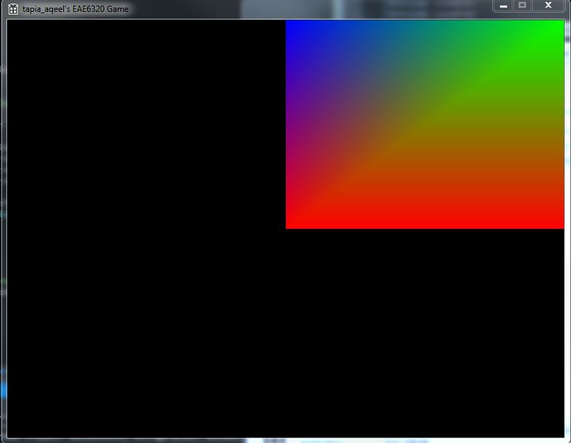 Leave a Reply. |
Aqeel TapiaThis is a blog that documents my work for my graphics Game Engineering class at the University of Utah. Archives
December 2015
Categories |
 RSS Feed
