|
As the semester comes to an end here I am with my version of a very simple first person shooter game. You can download the Direct3D_64 build here. You can download the OpenGL_32 build here. DESCRIPTION My game has a cross-hair and a gun modeled and textures. You can move yourself around using the WASD keys. There is a cool wooden floor that you can walk on. All this to show off my fancy new texturing system. I also have 2 spheres with different colors. You can shoot at them by hitting the SpaceBar button. They will gradually fade away the longer you keep shooting at them. The fancy pyramid just exists to look cool. Here's a screenshot: The ultimate goal of all of our assignments this semester was to be able to build an engine that someone else can use to make a game.
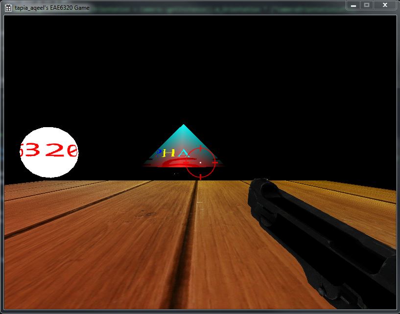
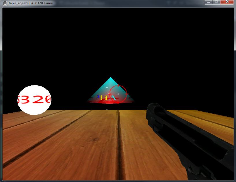
And to prove that everything works, we had to make a simple game. Since it was an engine of my own design, it was easy to work with a lot of things. With the way I had my systems set up, applying materials to each of the objects was fairly simple. We had a full description of what sort of object we are looking at in our material file and that got built at compile time. All the required assets would be loaded at run time from their binary formats very quickly. The material files for each mesh can get super complicated when you are dealing with multiple small meshes and textures since each mesh needs its own material file, but for the scope of this project and my game it was fine. Something else I would have done if I had more time was to add in more of the game code, like a win/loss state, more dynamic targets to shoot at etc. I was afraid of over scoping my initial project and not finishing it. That is why I decided to keep it simple, making sure it works as intended. This class was all about making our engine, with a focus on graphics. Working with Direct3D and OpenGl in the same engine was difficult. While I feel this did not give my enough opportunity to learn in-depth about Direct3D or OpenGL, working with C++ code to make sure that you are supporting 2 different platforms was interesting. Finding ways to have platform independent code and dependent code so that when modifying things, the code doesn't have to be changed in multiple places was challenging. Personally, I like to do my programming one step at a time. I build small systems first, using hardcoded values, and make sure the system as a whole works, before expanding to include additional features and less hardcoded, more dynamic systems. One of the problems with this approach is that you end up having to change a lot of your own code to incorporate the new systems. However, doing things step-by-step ensures that problems can be nipped in the bud. I also like this because I do not believing in building the most perfect engine, instead only adding scalability for things I am aware it needs to be scalable for. Sometimes this means I have to change things I have written before, but it helps me tackle problems a few at a time. The design of my code evolves as new features are added later on. Another limitation of this approach is that my engine also only contains functionality for things that are needed immediately. With the approach our professor has taken in teaching this class, there are a lot of things I learned about good design since we would have very descriptive requirements for what was needed. My programming knowledge and style has definitely improved over the course of this semester. At times, especially in the earlier assignments, it felt like I was simply following the instructions in the assignment to get it done without having to think much about how I would tackle a specific challenge. However, it also established a good base of code which we could expand upon in later assignments. Plus, since I was new to graphics programming, following instructions could also get complicated sometimes. That's all folks! I am ready for the holidays and done with my assignments. Wish you a Happy 2016! Thanks for reading! This week, I will added support for textures for the models we export from Maya and use in our game. We had to change a few things to make this happen. First, in our fragment shaders we need to add a "sampler" to sample our textures for a set of texture coordinates and render it onto the screen. These texture coordinates (obtained from Maya),, also known as UV coordinates help us map a texture to a mesh. I also added a texture builder that converts the textures into a DDS format that can be easily loaded by our Graphics API. The material builder we built last week also need to be modified since our material files now include a texture as well. The material builder loads the texture along with the sampler uniform so that the texture can be loaded along with the material and rendered. The image below shows my new material format in binary. The highlighted portion shows the new data that is added to my material file containing the name of my sampler and the texture. To use this data in my game I had to decide whether to make a separate class for the textures or merge this data as part of my material class. I decided to have the texture data along with my material data since it made more sense for me to have all of it in one place since I was reading it from the same file. The only reason I can think of why having a different texture class would be useful is if there are multiple textures on the same mesh. This scenario also seems highly unlikely in my project. Below are 2 screenshots comparing my game in Direct3D and OpenGl.. The textures look smoother on OpenGL and sharper on Direct3D. This is due to different default sampler states for each platform. The screenshots show the textures on my objects as part of my work for the game I am building for our final project. This is the last of our assignments. More on the final project next week.
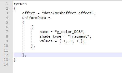
Download my current build here. I have controls for my upcoming game, so use the WASD to move the gun and space bar to shoot the spheres. Esc to quit. For this assignment we now created a material for our objects. This allows us to do things like “I want a table mesh with a wooden material”. Our engine now functions in this high-level design so that it is easy for a gameplay programmer to write code. This is also the main advantage of using materials. By encapsulating our effects inside our materials we can now change the looks of the objects by reusing the same effect files. For example, an effect consists of the shader files and render states used. The material can use these shaders to control the color and transparency (and later on the texture) for our objects rendered. The human readable file describes all the data about the materials used in the scene. Effect shows the effect path for our effect file. This is followed by our uniform data that shows the name of the uniform variable in the shader code and its corresponding values. This is then converted into a binary file that looks like this: The order in which I write my data is the effect path first. This is followed by the number of uniforms that are in the material file. Then I write out the data for each of the uniforms followed by a list of names for each of the uniform data. Once the binary files are read in, I set these uniforms individually during each draw call, since at these point I have access to all the uniform handles I need to set the data.
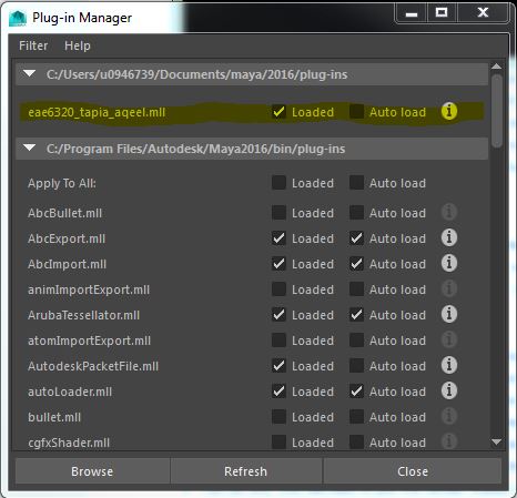
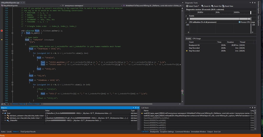
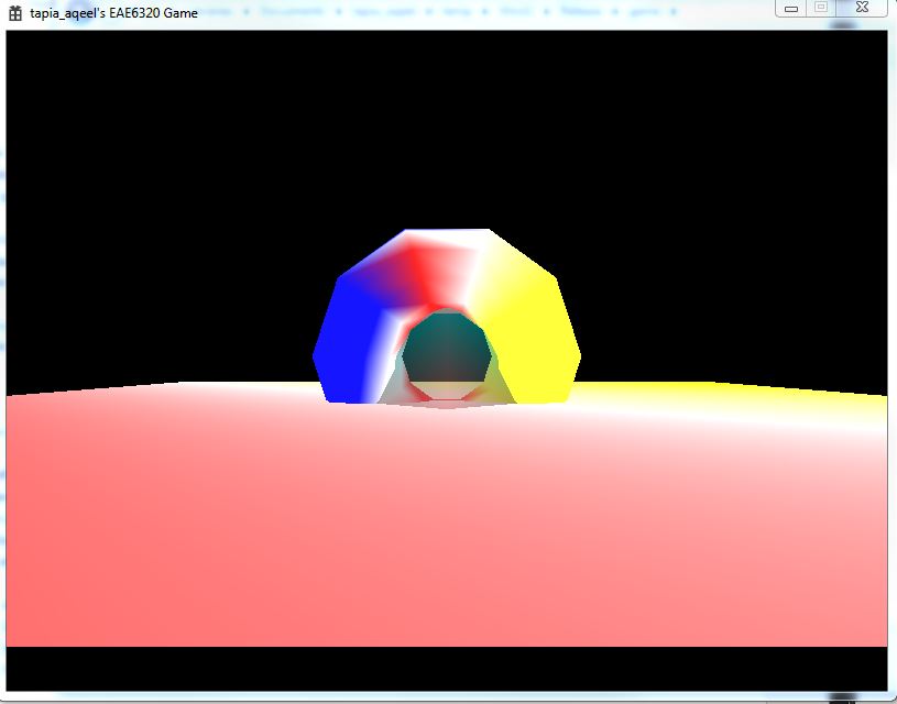
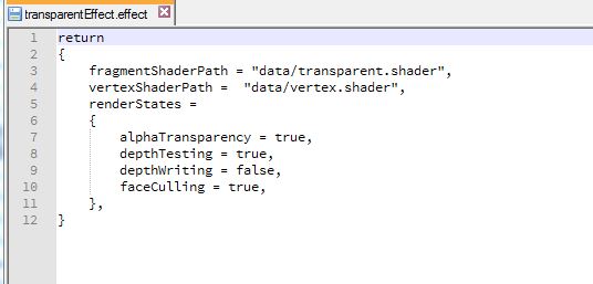
I had some problems with this assignment. As of now my OpenGl version displays a blank screen and my transparent shader doesn’t seem to work. I have spent close to 15 hours on this assignment. I am very tired now and will tackle these debugging problems later in the week. You can download the build I have so far here. Controls: WASD to move the camera in FPS style. Arrow keys to move the ring. Esc to quit. This week we made a huge visual upgrade to our assignment. Using a Maya exporter we can now export models directly out of Maya into the format of our human-readable files which can be read and used in our game. I must say, I enjoyed doing this assignment! The MayaMeshExporter project we added doesn’t depend on any of the other projects in our solution. It is a standalone exporter that we use from within Maya to export the model data into a format we can read. Here’s how we use it from Maya to load out plug-in. The plug-in is loaded and we use it to export our models. It will generate the mesh files in a format of our choice. The screenshot shows me debugging the exporter in visual studio. Another thing we added is the ability to display transparent objects in our scene. As you can see we have a transparent pyramid with the opaque torus showing through the transparent object. The torus covers parts of the transparent pyramid which are behind it. To achieve this we wrote a new transparent shader that created transparent files. To use this shader we created a new effect file that uses our old vertex shader and the transparent shader instead of the fragment shader. We also had to change the format of our effect files to include render states to control the following 4 settings through the effect file.
These values are stored in a single unsigned integer of 8 bits. This is because each bit represents a flag for each of the render states. Thus 4 out of these 8 bits are used for the 4 render states. The remaining 4 are currently unused. The images below show how they are written out in the binary files. The transparent mesh file contains a 0B which is 1011 in binary. The render states are set starting from the least significant bit as alpha transparency (set as true), followed by depth testing (set as true), depth writing(false) and face culling (true). As you can see from the previous image, reading in reverse order, the render states are set as true, false, true and true for each of the render states respectively which corresponds to 1011. We store these values easily in a single integer in this way.
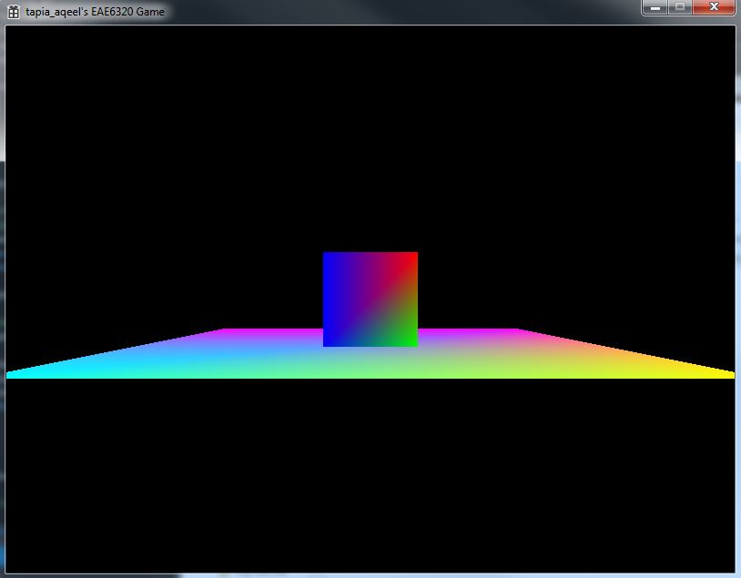
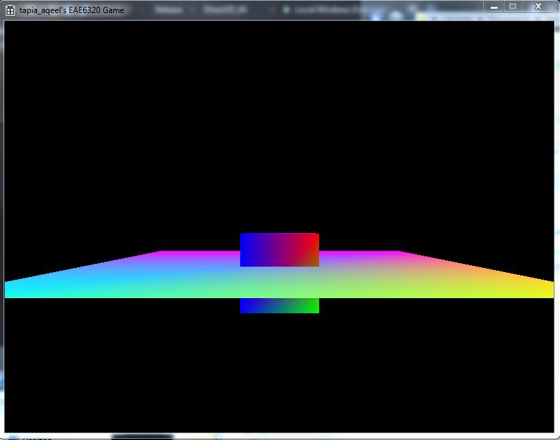
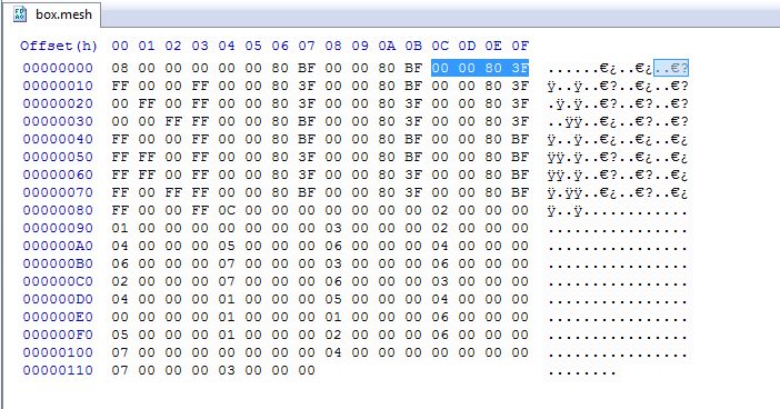
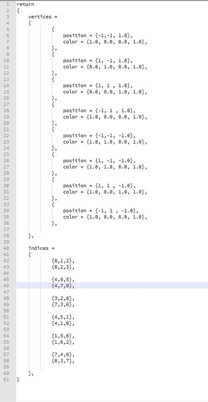
I placed the render states after the paths to the shaders because when I read them I store the current pointer for where I am reading from. It seemed easiest to just add code later on to access the states since I already know the current pointer. Another thing is, to make the files more human readable it made sense to show what shaders are being used before you set the render states. That way I know if I am using a transparent shader I need to set my alpha Transparency to true. Overview of alpha transparency: In computer graphics, alpha is the process of combining an image with a background to create the appearance of partial or full transparency. The alpha value (defined in our transparent shader) represents how much of the image is blended with the object. It is currently set to 0.5. That means half the image blends with the background i.e. 50% transparent. You can download the DirectX_64 build here. You can download the OpenGl_32 build here. Controls: WASD to move the camera in FPS style. Arrow keys to move the torus. Esc. to quit. This assignment took forever to complete, but the end result was fully worth it. I am now rendering 3D objects in my game!!! Woohoo! To achieve this 3D rendering one of the main changes we made to our system was the introduction of 3 new matrices to help us calculate the position of the objects and what to render on screen. 1. Local To World Transform All the objects which we make are in a neutral position, i.e. centered around the origin and the bottom face on the XZ plane. If we populate our game world with all these objects, all the objects would be at the origin. To move them, we use the Local-To-World transformation matrix to move those objects in relation to the actual location in the game world. This is calculated on basis of the object’s position and the orientation. 2. World To View TransformThis represents our game camera. If we display the objects as is in the game world, we would only see some of the objects and in a static, constant view. But we want to look around. We introduce the concept of a camera. Initially, without the matrix, we can assume the camera to be positioned at the origin and pointed towards positive Z. Using this transform we can move the camera around thereby changing our view position relative to the objects. 3. View To Screen Transform This transform helps us decide what, out of all the objects we have, to display on our screen. To do this we need 4 main things, a field of view to render things the camera is looking at and an aspect ratio that normalizes the distances in different directions. We also need a near and far plane such that objects too close and too far from the camera are not rendered. If we draw the plane first, the intersection will not occur and the box will be on top of the plane, which is undesirable. This is remedied by the Depth Buffer. The depth buffer and depth testing allows us to draw the objects in any order, and not worry about what will get rendered first, and on top of whom. A depth buffer contains data pertaining to the z depth of each pixel rendered. If two rendered objects overlap each other, then the depth testing is performed to decide which pixel is closer to the camera. The above 2 images show my Box mesh files in binary and human readable format. The highlighted numbers in the image shows the Z values that were added to my binary file for this assignment.
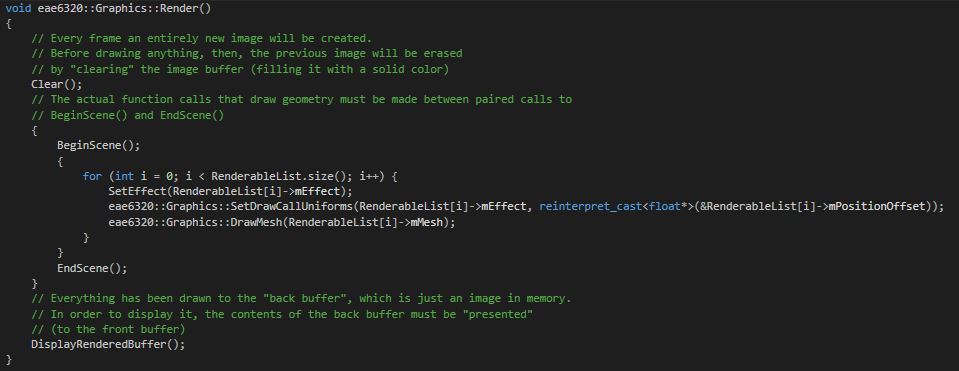
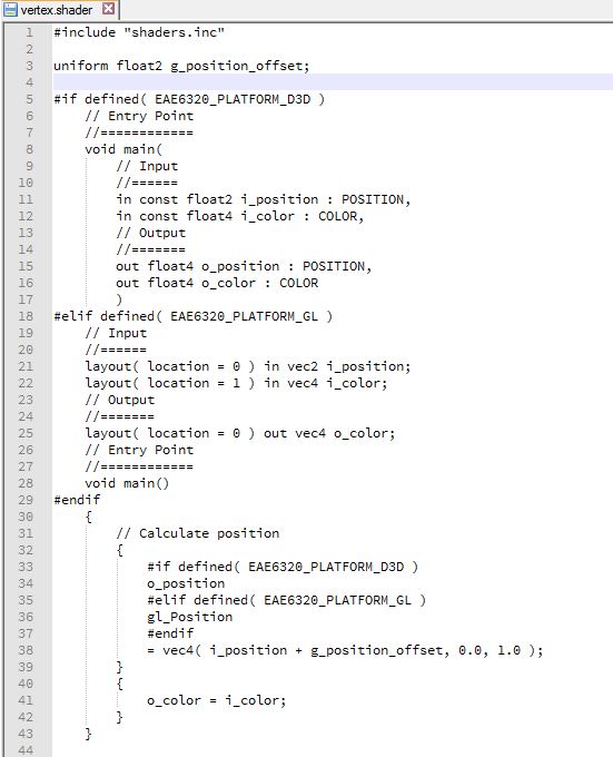
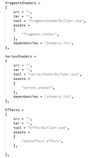
I also created a camera class that allows the user to control what part of the game space he is looking at. The camera class exists as part of my graphics code but now that I think about it, it may not be the best place to have the camera code. It works for now so I am leaving it there. Download the DirectX build here. Download the OpenGL build here. CONTROLS: Arrow keys to move the object. WASD to move the camera in First-person shooter camera style. Esc to quit. This assignment was relatively simpler and required more redesigning of code. The main redesign was to make our Render() function completely platform independent so as to hide the platform specific code. I chose to make different functions for each of portions since for the most part Direct3D and OpenGl follow the same overall idea implemented in different ways. The specific code is written in each of these separate functions which are called from the Render loop. It then loops through all my renderable objects for bind effects and draw meshes. The image below shows how my implementation looks: The next part was to make our shader code platform independent as far as possible. Using ifdef’s we can make the main loop fairly platform independent as shown. I decided to use vec4 in my main loop since vector4 seems more descriptive to me than float4. Another thing we did to make for platform independent code is to use an include file that has things common to both shaders. To make sure that every time our include file is changed we are also rebuilding our shaders we had to make some tweaks to when our shaders are being rebuilt. Currently, if our shaders are modified after they are built we need to rebuild them. Now, we perform the same check for any files our shaders depend on as well. We do this by adding dependencies for each asset we need to rebuild as shown in the image below.
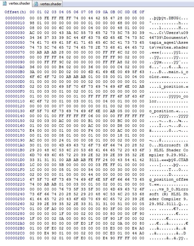
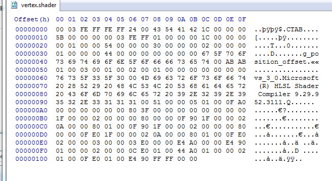
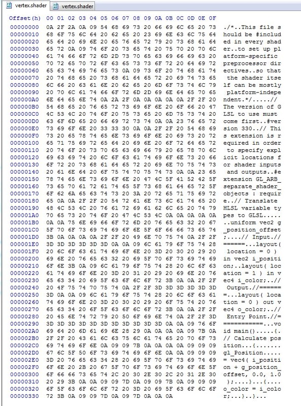
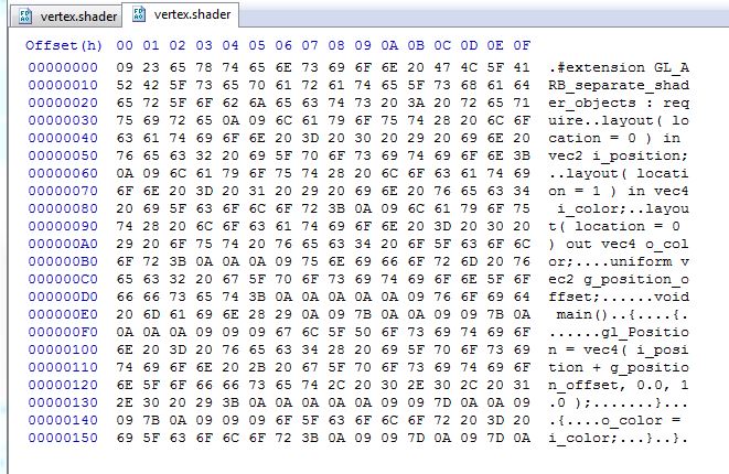
Our game still looks the same as the last assignment. However there are a lot of code design changes we made this week. The first step was to make a human readable effect file, an effect builder that makes it a binary file and using it in our game. The images below show my human-readable effect file and its corresponding binary file as generated by the EffectBuilder tool that we created for this assignment. I named my effect file “mesheffect.effect”. I wanted to have the .effect extension but since we had only one effect for all of my meshes it didn’t seem to matter what I called it, hence the name. The paths are stored in null terminated strings “\0” in the binary format. So the format is, fragment shader path – null terminator – vertex shader path – null terminator. Thus, I can easily extract the information from the binary files. The other portion of the assignment was to create a shader builder. Currently our shaders are being compiled at run time. This code is moved to a ShaderBuilder tool which will compile them at build time. I have 2 slightly different builders of the same Shader Builder code for my Fragment and Vertex shaders since using a single shader builder would require me to pass more arguments in my AssetsToBuild.lua file to differentiate between the 2 shaders. I am more comfortable working in C++ than in Lua hence I chose the one that suited my preferences. Our builders have a different #define to build debug shaders versus release shaders. The debug shaders contain far more data than the release shaders that is not necessary for a release build where optimization and small shader size is important. That data does contain information like the location from where the shader was compiled, etc. that would help in a debugging build. The images below show the difference. The GLSL shaders for OpenGL have a far more noticeable difference. All the comments in the shader file are maintained in the debug build versus the release build. This extra data can help in debugging but is not required for the game to run. The images below show the difference.
Uniform variables are used to communicate with the vertex or fragment shader from "outside". Using a uniform we can access the position of our objects inside the shader from our c++ code. We use this to manipulate the co-ordinates of the object to change the position it is rendered on screen. The uniform functions as a pool of resources that are always available, thus they can be changed after the mesh is built. Rather than changing the vertex data every frame (which is expensive) we can simply add an offset to its position using the uniform and change the place where they are rendered on screen. This is also useful if our mesh is very large. For more vertices, we have a large number of vertex data stored. Iterating through every vertex to modify it every frame is expensive.
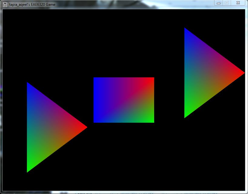
My build now looks like in the image below. You can download the DirectX_64 version here. You can download the OpenGL_32 version here. Controls: Use Arrow keys on the keyboard to move the square around. For this week's assignment the objective was to convert our human readable mesh file into a binary data format which can be accessed at run time to generate our meshes in the game. 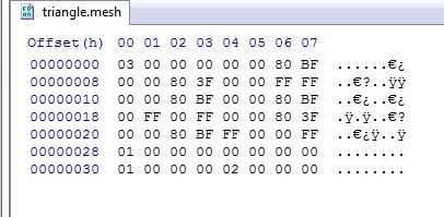 The image shows the format of my binary file. I have placed the data in the following order: Number of vertices Vertex Data Number of Triangles Index Data I chose this particular format because that was the order in which I was reading the files from the human readable mesh files. So it was convenient to just write it into the binary file in the same order. The number of elements in the array need to be in the file before the array data so that when reading the data we know how many bytes contain vertex data. In this file the triangle mesh contains 3 vertices as shown with the first 8 digits (03 00 00 00) corresponding to 4 bytes (32 bits) of data. Since each vertex contains 2 floats (x,y) and 4 colors (r, g, b, a), a total of 12 bytes of data, we know that the next 12x3 bytes of data contain data about the 3 vertices. Here are some of the advantages of using binary files:
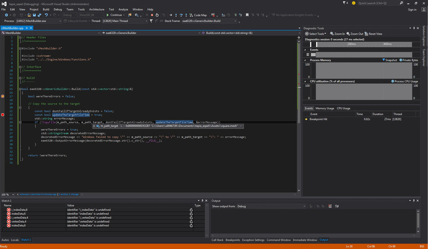
The build binary mesh files are different for each platform. The only difference I had in my files was the winding order of the indices. Since OpenGL uses a winding order opposite to DirectX when I write to my binary files I have a different winding order for each platform based on whether it uses a clockwise (Direct_X) or counter-clockwise (OpenGL) format so that it can be read easily during run-time without having to worry about the order of the listed indices. 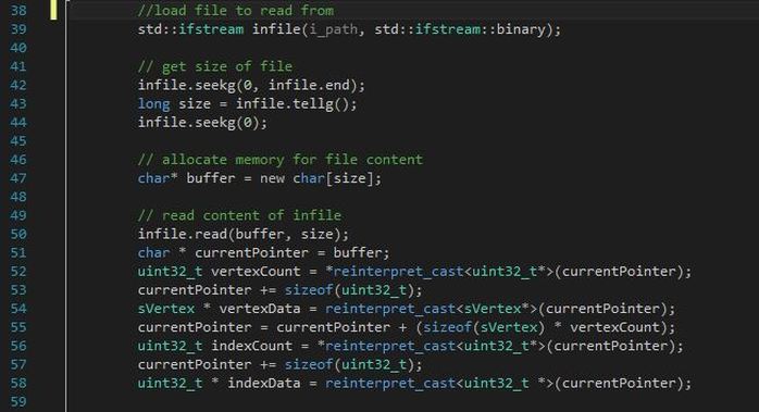 The image below shows my implementation of extracting the data from the binary file at run time. I am creating a current pointer to the location that starts at the beginning of the file. I know the first 4 bytes are the number of vertices (3 in this case) I have in my mesh so I read the first 4 bytes into the corresponding variable. I then increment the current pointer to point to the address location after the first 4 bytes. That gives me the vertex data for each of the 3 vertices I have, and so on... We also set up our shader system so it has a platform independent interface. I created a struct that has the following functionality to load the shaders into the game. - LoadEffect (sEffect, "data/fragment.shader", "data/vertex.shader"); - SetEffect (sEffect); The LoadEffect function takes in the paths for the shader files and loads the vertex shader and fragment shader. The SetEffect function is used to set the shaders to display our meshes on screen. The function calls remain the same regardless of the platform. Download the DirectX_64 build here Download the OpenGL_32 build here For this assignment we had to remove the use of custom command line arguments to pass the assets. Instead we created a new file that contains a list of all the assets required to be built. We built a mesh builder tool that we use to build our meshes and add to the asset list. We also added another mesh, a triangle to our list of meshes being output on the screen. 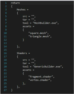 This is how I decided to structure my file called AssetsToBuild.lua that contains all the data about the assets to build. like which builder tool to use to build them, the source path (src), target path (tar) and the list of those type of assets. The assets are grouped by type so all the mesh assets are together and all the shaders are grouped together. That way we can specify common information for all of the assets instead of repeating it for each asset. I placed this file in the Scripts folder. The reason being that since my BuildAssets.lua, (the script that actually builds the assets using lua functions) script is in this folder it made most sense to have the AssetsToBuild.lua in the same folder. That way all my lua scripts are in the same folder. The screenshot below shows me debugging the MeshBuilder. To do this we need to specify custom command line arguments to the Debugger, set the desired builder to be debugged as the startup project and then debug this using visual studio. This is required in case a specific asset builder needs to be debugged. These are the new command line arguments for the BuildAssets.lua project.
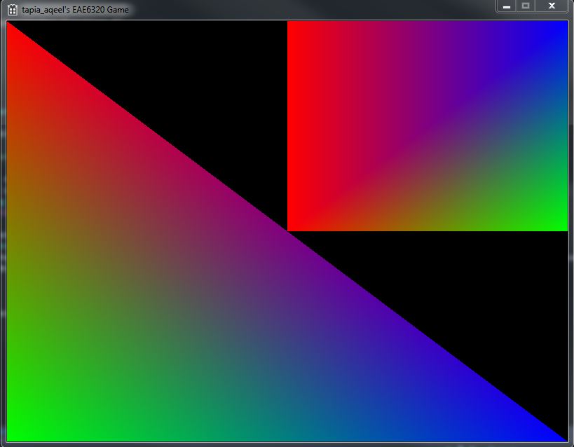
"$(BinDir)AssetBuilder.exe" We pass the AssetBuilder.exe application as an argument. This is because the asset builder contains the list of assets as well as all the code to build our assets. Hence no other arguments need to be passed. The AssetBuilder project depends on the BuilderHelper.. The BuilderHelper contains helper functions and utility functions that are used for the build process. Additionally it uses the Windows and Lua libraries and depends on those to build as well. UPDATE : After talking to my professor John-Paul, I realized the MeshBuilder/GenericBuilder need to be built to provide the assets for the asset builder to build. The asset builder does NOT require these builder tools to build, but it does need it to run correctly since they provide the assets the asset builder needs. Below is the screenshot of my output, now using 2 meshes, a triangle and square. These meshes can now be easily added to the game using a simple lua script as shown above. You can download the Direct3D_64 build here. You can download the OpenGL_32 build here |
Aqeel TapiaThis is a blog that documents my work for my graphics Game Engineering class at the University of Utah. Archives
December 2015
Categories |






 RSS Feed
