|
For this assignment we now created a material for our objects. This allows us to do things like “I want a table mesh with a wooden material”. Our engine now functions in this high-level design so that it is easy for a gameplay programmer to write code. This is also the main advantage of using materials. By encapsulating our effects inside our materials we can now change the looks of the objects by reusing the same effect files. For example, an effect consists of the shader files and render states used. The material can use these shaders to control the color and transparency (and later on the texture) for our objects rendered. The human readable file describes all the data about the materials used in the scene. Effect shows the effect path for our effect file. 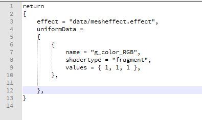 This is followed by our uniform data that shows the name of the uniform variable in the shader code and its corresponding values. This is then converted into a binary file that looks like this: 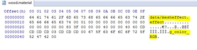 The order in which I write my data is the effect path first. This is followed by the number of uniforms that are in the material file. Then I write out the data for each of the uniforms followed by a list of names for each of the uniform data. Once the binary files are read in, I set these uniforms individually during each draw call, since at these point I have access to all the uniform handles I need to set the data.
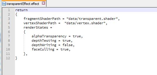
I had some problems with this assignment. As of now my OpenGl version displays a blank screen and my transparent shader doesn’t seem to work. I have spent close to 15 hours on this assignment. I am very tired now and will tackle these debugging problems later in the week. You can download the build I have so far here. Controls: WASD to move the camera in FPS style. Arrow keys to move the ring. Esc to quit. This week we made a huge visual upgrade to our assignment. Using a Maya exporter we can now export models directly out of Maya into the format of our human-readable files which can be read and used in our game. I must say, I enjoyed doing this assignment! The MayaMeshExporter project we added doesn’t depend on any of the other projects in our solution. It is a standalone exporter that we use from within Maya to export the model data into a format we can read. Here’s how we use it from Maya to load out plug-in. 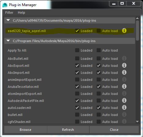 The plug-in is loaded and we use it to export our models. It will generate the mesh files in a format of our choice. The screenshot shows me debugging the exporter in visual studio. 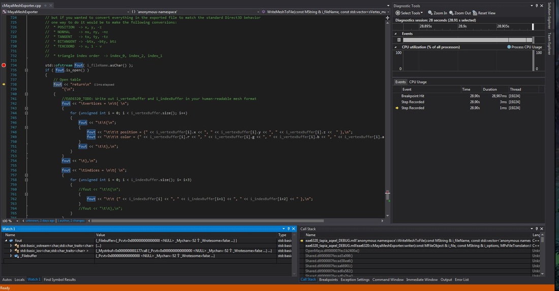 Another thing we added is the ability to display transparent objects in our scene. As you can see we have a transparent pyramid with the opaque torus showing through the transparent object. The torus covers parts of the transparent pyramid which are behind it. 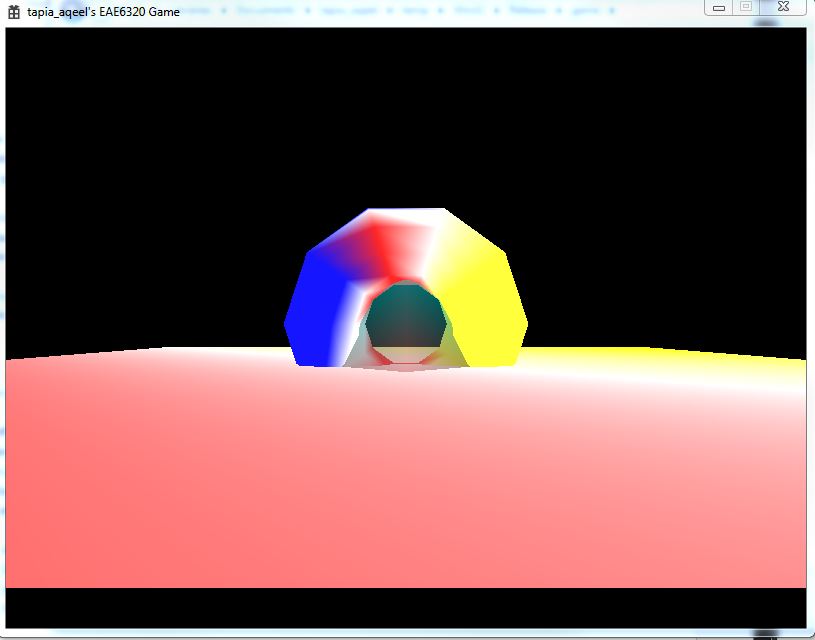 To achieve this we wrote a new transparent shader that created transparent files. To use this shader we created a new effect file that uses our old vertex shader and the transparent shader instead of the fragment shader. We also had to change the format of our effect files to include render states to control the following 4 settings through the effect file.
 These values are stored in a single unsigned integer of 8 bits. This is because each bit represents a flag for each of the render states. Thus 4 out of these 8 bits are used for the 4 render states. The remaining 4 are currently unused. The images below show how they are written out in the binary files.
The transparent mesh file contains a 0B which is 1011 in binary. The render states are set starting from the least significant bit as alpha transparency (set as true), followed by depth testing (set as true), depth writing(false) and face culling (true). As you can see from the previous image, reading in reverse order, the render states are set as true, false, true and true for each of the render states respectively which corresponds to 1011. We store these values easily in a single integer in this way.
I placed the render states after the paths to the shaders because when I read them I store the current pointer for where I am reading from. It seemed easiest to just add code later on to access the states since I already know the current pointer. Another thing is, to make the files more human readable it made sense to show what shaders are being used before you set the render states. That way I know if I am using a transparent shader I need to set my alpha Transparency to true. Overview of alpha transparency: In computer graphics, alpha is the process of combining an image with a background to create the appearance of partial or full transparency. The alpha value (defined in our transparent shader) represents how much of the image is blended with the object. It is currently set to 0.5. That means half the image blends with the background i.e. 50% transparent. You can download the DirectX_64 build here. You can download the OpenGl_32 build here. Controls: WASD to move the camera in FPS style. Arrow keys to move the torus. Esc. to quit. This assignment took forever to complete, but the end result was fully worth it. I am now rendering 3D objects in my game!!! Woohoo! 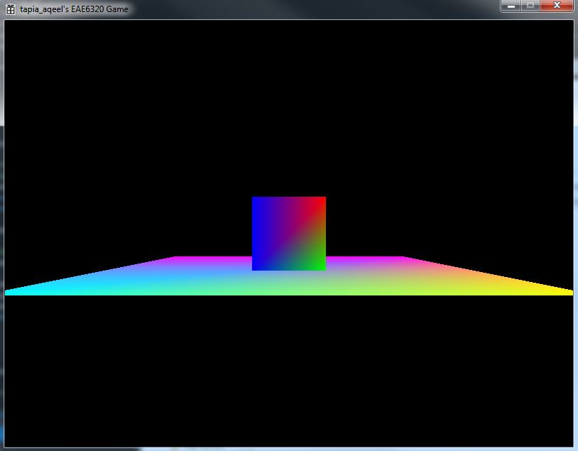 To achieve this 3D rendering one of the main changes we made to our system was the introduction of 3 new matrices to help us calculate the position of the objects and what to render on screen. 1. Local To World Transform All the objects which we make are in a neutral position, i.e. centered around the origin and the bottom face on the XZ plane. If we populate our game world with all these objects, all the objects would be at the origin. To move them, we use the Local-To-World transformation matrix to move those objects in relation to the actual location in the game world. This is calculated on basis of the object’s position and the orientation. 2. World To View TransformThis represents our game camera. If we display the objects as is in the game world, we would only see some of the objects and in a static, constant view. But we want to look around. We introduce the concept of a camera. Initially, without the matrix, we can assume the camera to be positioned at the origin and pointed towards positive Z. Using this transform we can move the camera around thereby changing our view position relative to the objects. 3. View To Screen Transform This transform helps us decide what, out of all the objects we have, to display on our screen. To do this we need 4 main things, a field of view to render things the camera is looking at and an aspect ratio that normalizes the distances in different directions. We also need a near and far plane such that objects too close and too far from the camera are not rendered. 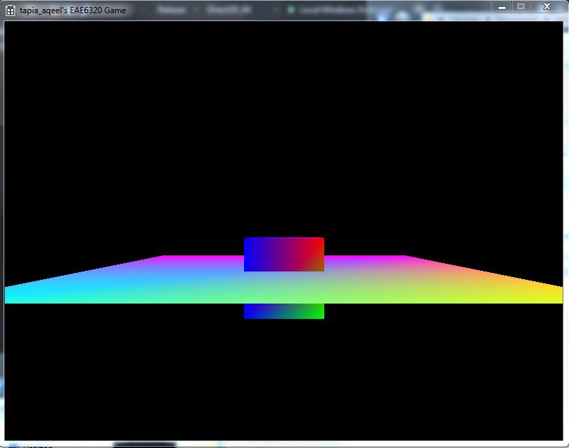 If we draw the plane first, the intersection will not occur and the box will be on top of the plane, which is undesirable. This is remedied by the Depth Buffer. The depth buffer and depth testing allows us to draw the objects in any order, and not worry about what will get rendered first, and on top of whom. A depth buffer contains data pertaining to the z depth of each pixel rendered. If two rendered objects overlap each other, then the depth testing is performed to decide which pixel is closer to the camera. 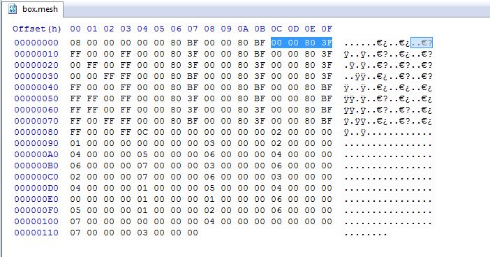 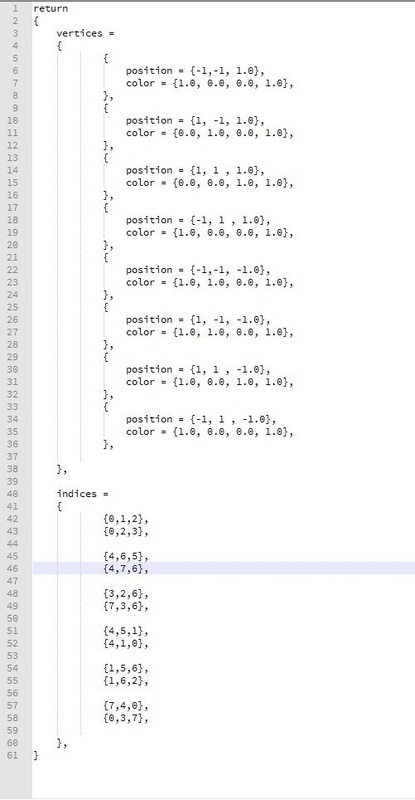 The above 2 images show my Box mesh files in binary and human readable format. The highlighted numbers in the image shows the Z values that were added to my binary file for this assignment.
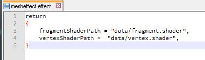
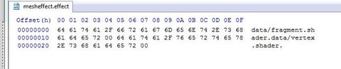
I also created a camera class that allows the user to control what part of the game space he is looking at. The camera class exists as part of my graphics code but now that I think about it, it may not be the best place to have the camera code. It works for now so I am leaving it there. Download the DirectX build here. Download the OpenGL build here. CONTROLS: Arrow keys to move the object. WASD to move the camera in First-person shooter camera style. Esc to quit. This assignment was relatively simpler and required more redesigning of code. The main redesign was to make our Render() function completely platform independent so as to hide the platform specific code. I chose to make different functions for each of portions since for the most part Direct3D and OpenGl follow the same overall idea implemented in different ways. The specific code is written in each of these separate functions which are called from the Render loop. It then loops through all my renderable objects for bind effects and draw meshes. The image below shows how my implementation looks: 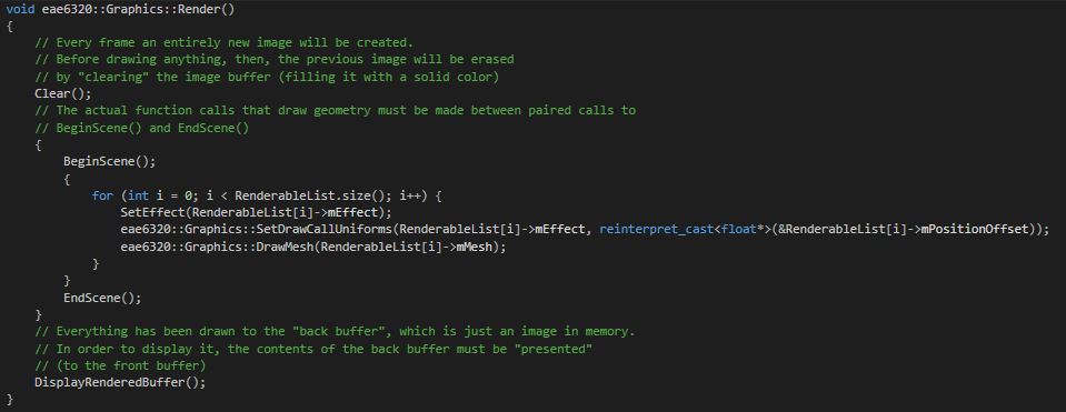 The next part was to make our shader code platform independent as far as possible. Using ifdef’s we can make the main loop fairly platform independent as shown. I decided to use vec4 in my main loop since vector4 seems more descriptive to me than float4. 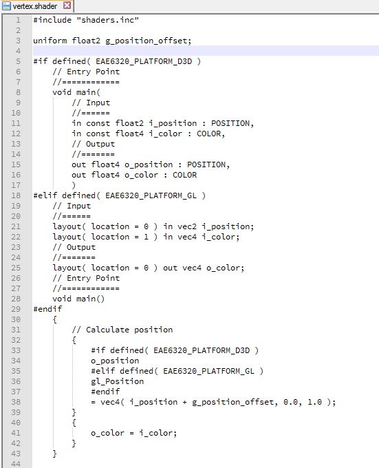 Another thing we did to make for platform independent code is to use an include file that has things common to both shaders. To make sure that every time our include file is changed we are also rebuilding our shaders we had to make some tweaks to when our shaders are being rebuilt. Currently, if our shaders are modified after they are built we need to rebuild them. Now, we perform the same check for any files our shaders depend on as well. We do this by adding dependencies for each asset we need to rebuild as shown in the image below. 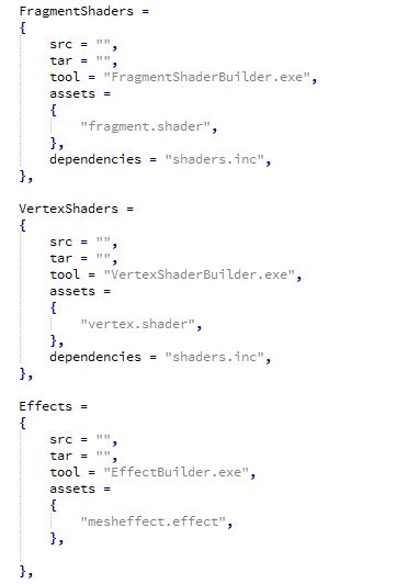 Our game still looks the same as the last assignment. However there are a lot of code design changes we made this week. The first step was to make a human readable effect file, an effect builder that makes it a binary file and using it in our game. The images below show my human-readable effect file and its corresponding binary file as generated by the EffectBuilder tool that we created for this assignment. I named my effect file “mesheffect.effect”. I wanted to have the .effect extension but since we had only one effect for all of my meshes it didn’t seem to matter what I called it, hence the name. The paths are stored in null terminated strings “\0” in the binary format. So the format is, fragment shader path – null terminator – vertex shader path – null terminator. Thus, I can easily extract the information from the binary files.
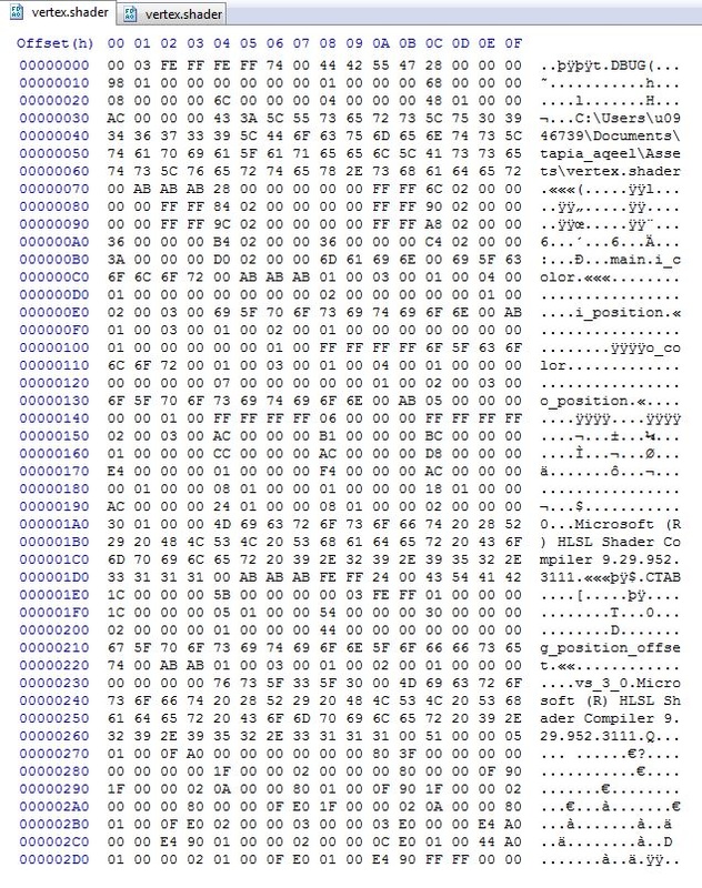
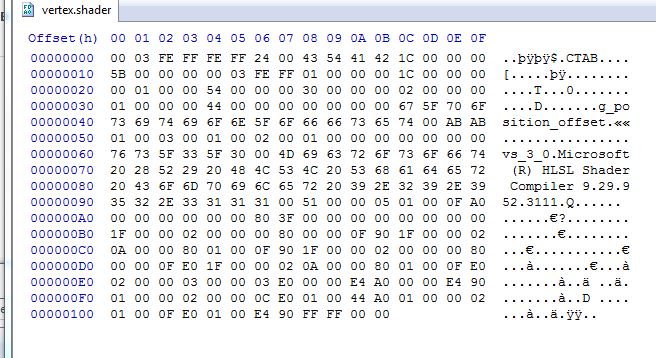
The other portion of the assignment was to create a shader builder. Currently our shaders are being compiled at run time. This code is moved to a ShaderBuilder tool which will compile them at build time. I have 2 slightly different builders of the same Shader Builder code for my Fragment and Vertex shaders since using a single shader builder would require me to pass more arguments in my AssetsToBuild.lua file to differentiate between the 2 shaders. I am more comfortable working in C++ than in Lua hence I chose the one that suited my preferences. Our builders have a different #define to build debug shaders versus release shaders. The debug shaders contain far more data than the release shaders that is not necessary for a release build where optimization and small shader size is important. That data does contain information like the location from where the shader was compiled, etc. that would help in a debugging build. The images below show the difference.
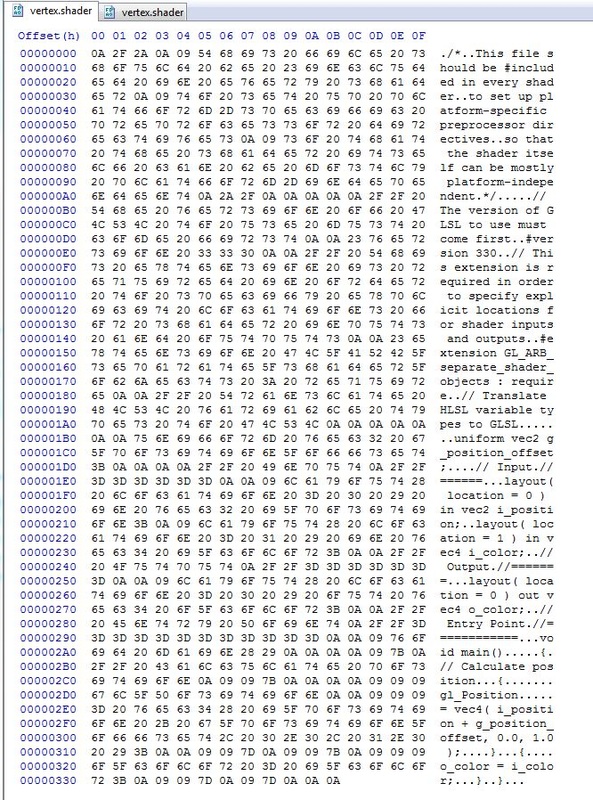
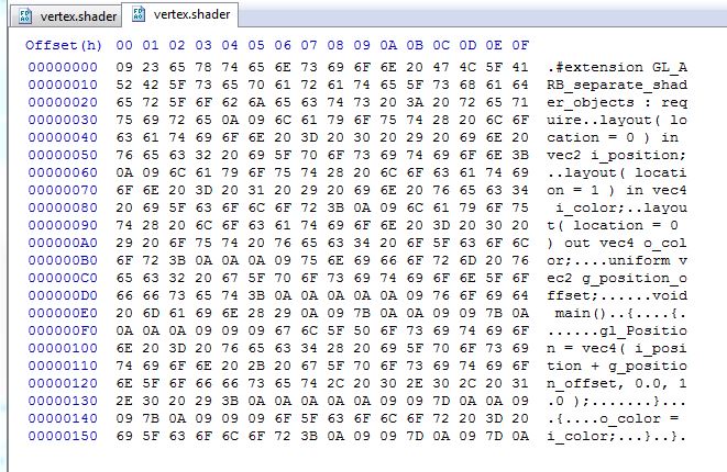
The GLSL shaders for OpenGL have a far more noticeable difference. All the comments in the shader file are maintained in the debug build versus the release build. This extra data can help in debugging but is not required for the game to run. The images below show the difference.
|
Aqeel TapiaThis is a blog that documents my work for my graphics Game Engineering class at the University of Utah. Archives
December 2015
Categories |


 RSS Feed
